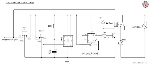
You may wonder if it is possible to control a light using a remote controller. In this article CircuitsGallery presenting an interesting DIY circuit that helps you to turn ON and OFF a lamp with a remote controller.
Here we have made use TSOP, an IR receiver, which detects the IR rays from the remote. NE555 is the next important part which produces a clock pulse for toggling the D flip flop.
The relay helps to connect any electrical devises to the circuit and you can control any electrical equipment not only a light.
You must need regulated power supply of 5 volt to do this circuit because TSOP require 5v. Its voltage should not exceed 5V.
- Similar Circuit: Clap switch Circuit
Circuit Diagram of Remote Control Light

Click on the image for enlarged view
Components Required
- 230v to 6v step down transformer
- 7805 voltage regulator
- TSOP IR receiver
- IC 555
- IC 7474
- BC 187 Transistor
- Diode 1N4007x5
- Resistors (220KΩ, 100Ω)
- Relay (6V)
- Capacitor (1μF, 470μF)
Working of Remote Control Light Switch
- Power supply circuit is not shown here. 1st you build a Rectifier circuit for 6v DC and proceed.
- Maximum voltage of TSOP and 7474 is 5V hence we are using 7805 voltage regulator IC to get constant 5V DC.
- The output of TSOP is always 5V, and the output will be zero when IR rays strikes on it.
- 555 IC biased as a Monostable Multivibrator. Normally its output is 0V (ground potential), provided that voltage at the 2nd pin must be greater than 1/3Vcc.
- When the voltage at the 2nd pin goes below 1/3Vcc output switches to high (5V) for the time T=1.1RC after the time interval output returns to 0V again.
- The D-flip flop7474 is wired as Toggle mode, i.e. Q' to D input. 555 used as clock generator to the flip flop.
- When it get a clock pulse Output goes to High and remain in that state until it get next pulse.
- On receiving next pulse output goes to low and remain in that state till the next pulse.
- This process will continue.
- Output of 7474 is fed to base terminal of BC 187 which is driver transistor, when it base voltage is high current will flow through the load
- Here relay is the load and it will energize only when the base voltage of BC 187 is high and connects the 230v AC supply to the Bulb or light.
(Read More: How to Connect relay in circuit)
- Diode Df is freewheeling diode used to dissipate the stored energy in the inductor load. It is essential for the smooth working of this circuit
Components Pin out
Ads


+Circuit+diagram+using+CD4047+and+IRFZ44+power+MOSFET.png)


is there a circuit diagram for remote control of remote control light?
ReplyDeletein ic 7474 we must gice connections for VCC and GND plz tell it
ReplyDeleteIt's clearly given there in the circuit diagram i.e. 7th pin-Ground and 14th pin-Vcc(+5V)
Deleteyou didnt publish the IR Transmitter circuitry please add it
ReplyDeleteHi Kartik,
DeleteYou can use any TV or CD player remote control for the purpose, we will publish the IR transmitter circuit of different types soon. Keep visiting
Hi Kartik,
DeleteGlad to inform you that we have added the transmitter circuit. Check this out IR Transmitter and Receiver Circuit
please add the ir transmitter circuitry also
ReplyDeleteWe will add it soon.
DeletePlease check the link in the above comment.
Delete