

What is DAC? Digital to analog converter (DAC) is used to get analog voltage corresponding to an input digital data. Data in binary digital form can be converted to corresponding analog form by using a R-2R ladder (binary weighted resistor) network and a summing amplifier. It is more common and practical. Below is the circuit and output simulated waveform of R-2R ladder network DAC. This circuit also uses an op amp (741) summing amplifier circuit.
You can learn how to build a Digital to Analog converter using the simple technique explained in this page. Actually different types of Digital to Analog converter ICs are available commercially based on this same principle. The R-2R ladder network is build by a set of resistors of two values. It makes the circuit more simple and economical for different applications.
You can learn how to build a Digital to Analog converter using the simple technique explained in this page. Actually different types of Digital to Analog converter ICs are available commercially based on this same principle. The R-2R ladder network is build by a set of resistors of two values. It makes the circuit more simple and economical for different applications.
Circuit Diagram

Components Required
- Resistors (1KΩx4, 2KΩx5)
- 741 Op Amp
- 7493 Counter IC
Working of R-2R ladder network DAC
- R-2R weighted resistor ladder network uses only 2 set of resistors- R and 2R. If you want to build a very precise DAC, be precise while choosing the values of resistors that will exactly match the R-2R ratio.
- This is a 4 bit DAC. Let us consider the digital data D3D2D1D0= 0001 is applied to the DAC, then the Thevenin equivalent circuit reduction is shown below.

- Vref is nothing but the input binary value reference voltage, that is for binary 1, Vref=5V and for binary 0, Vref=0V.
- For 0001 only D0=Vref, all other inputs are at 0V and can be treated as ground. So finally Vref/16 volt is appearing as the input to op amp. This value gets multiplied by the gain of op amp circuit – (Rf/Ri).
- If we proceed in this manner (Thevenin equivalent reduction), we will get

- Note that you can build a DAC with any number of bits you want, by simply enlarging the resistor network, by adding more R-2R resistor branches.
- In this circuit the 7493 IC simply provides digital inputs to DAC. It is a counter IC and not an integral part of the DAC circuit. You can apply any combinations of binary inputs to D3D2D1D0
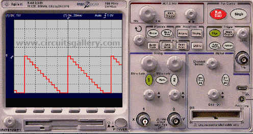
Output waveform

Components pin out


i-St@r Lab
Ads


+Circuit+diagram+using+CD4047+and+IRFZ44+power+MOSFET.png)

0 comments:
Post a Comment