

Filter circuits are used to pass only certain frequency components. In a RC Low Pass Filter (LPF), only LOW frequency components from the input signal are passed to output, whereas HIGH frequencies get attenuated.
This article gives an idea about low pass filter using resistor capacitor combination (RC Filter).
Op amp low pass filters are also used to decrease the slope or to get a sharp cutoff frequency along with amplification. We had discussed about Op-Amp Low Pass Filter already.
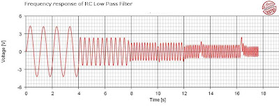
Here is the most simple but common filter circuit using RC network with frequency response. The given waveform shows decreasing of gain with increasing frequency.


This article gives an idea about low pass filter using resistor capacitor combination (RC Filter).
Op amp low pass filters are also used to decrease the slope or to get a sharp cutoff frequency along with amplification. We had discussed about Op-Amp Low Pass Filter already.
Here is the most simple but common filter circuit using RC network with frequency response. The given waveform shows decreasing of gain with increasing frequency.
RC Low Pass Filter Circuit
Components Required for RC LPF
- Resistor
- Capacitor
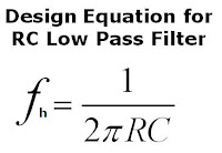
RC Low Pass Filter Design

LOW Pass Filter (LPF) Working
- It allows passing low frequency components and attenuates high frequency components in the input signal.
- The capacitive reactance is given by, Xc=1/(C(2πf). That is capacitive reactance decreases with increase in frequency (Inversely proportional).
- Now at higher frequencies, the capacitor acts as a virtual short circuit which directs the input signal amplitude to ground. Thus the output falls to zero.
- At lower frequencies capacitor acts as an open circuit, and the entire signal appear at the output.
- By observing the above wave form you can see that the amplitude decreases with increase in frequency.
Frequency Response of RC Low Pass Circuit


Click on the image to enlarge
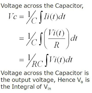
RC Low Pass Filter working as an Integrator
- The same circuit can be treated as an Integrator.
- An integrator does the mathematical operation 'Integration' of the input signal.

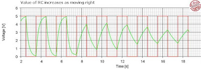
- When pulse waveform is applied to the circuit, capacitor charges through the resistor and hence the output voltage builds up.
- When the input is removed (ground potential), capacitor starts to discharge.
- Thus we get a triangular waveform.

Click on the image to enlarge
- As the value of RC increases amplitude of the output decreases (See above fig) because it take more time to charge and discharge.
Components Pin-out
Ads

+Circuit+diagram+using+CD4047+and+IRFZ44+power+MOSFET.png)


